Lesson: Holiday Lights and Circuits
 (Lesson courtesy TeachEngineering). Grade Level: 4-9. Group Size: 2. Time Required: 1 hour. Cost Per Group: Approximately $ 20. Lesson PDF.
Overview
Students in grades 4-8 build simple circuits using a battery, wires, and light bulbs. They examine how electricity is conducted through a light bulb using a battery as a power source, and learn the difference between a series circuit and a parallel circuit. This introduction to circuits serves as a good introduction to electrical engineering, as every electrical device has a circuit designed by an electrical engineer.
Learning Objectives
At the end of the activity, the students should be able to distinguish the difference between a parallel circuit and a series circuit.
North Carolina Science Standards (2004)
Grade 4
3.03 Design and test an electric circuit as a closed pathway including an energy source, energy conductor, and an energy receiver.
3.08 Observe and investigate the ability of electric circuits to produce light, heat, sound, and magnetic effects.
3.06 Describe and identify materials that are conductors and nonconductors of electricity.
3.07 Observe and investigate that parallel and series circuits have different characteristics.
3.09 Recognize lightning as an electrical discharge and show proper safety behavior when lightning occurs.
Materials List
- One set of Christmas lights
- One alkaline lantern battery per group (6 Volts)
- 6 alligator clips or wires
- 2 to 3 light bulbs per group (whatever size will fit into the light bulb holder) 1 light bulb holder per light bulb (can be found on the website: www.hometrainingtools.com)
Vocabulary/Definitions
Circuit : A path through which electrical current can flow.
Circuit Diagram : An illustrative picture used to explain the paths through which electricity can flow.
Conductor: A material that allows for electrical current to flow.
Current: The flow of electrons through a condutor.
Electricity: A source of power generated from the flow of electrical current.
Electron: A small, atomic particle with a negative charge.
Energy: The ability to do work.
Background
(from the TeachEngineering lesson “Electrifying the World”)
All matter is made up of atoms. An atom consists of a nucleus in the center, which is comprised of positively charged and uncharged particles. The uncharged particles are called neutrons and the positively charged particles are called protons. Surrounding the nucleus are negatively charged particles called electrons. There are an equal number of protons and electrons. Observe the picture of an atom. 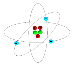 The nucleus is represented in the center by the red and yellow dots, and the electrons are represented by the blue dots.
Something important to remember is that opposite charges attract one another and like charges repel one another. In other words, protons are attracted to electrons and repelled by other protons. Likewise, electrons are attracted to protons and repelled by other electrons.
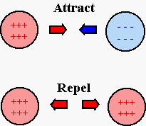 This phenomenon is caused by what is known as an electric force. Most matter has no overall electrical charge because of the balance between the number of protons and electrons. However, when the balance of the electrical force between protons and electrons is disturbed by another force (e.g. magnetic forces) an atom may gain or lose an electrical charge. When this occurs, the atom will either have an overall negative or overall positive charge. The atom in this state is now called an ion. Now that the atom has an overall electrical charge it will interact with other charged ions in the same manner as described earlier. In other words, oppositely charged ions will attract one another, and like ions will repel one another.
The loss in electrical charge from an atom allows for the free movement of electrons. The movement of electrons creates what is called current. Electricity is a source of power generated from the flow of electrical current. When a material called a conductor is placed between two charged objects, the loose electrons are pushed away by the negatively charged object, and the electrons are then drawn into the positively charged object. There are many different types of conductors. An example of a good conductor is metal, which is the reason why wiring is made out of metal. Water is also a conductor, and since the human body contains a lot of water, it is too!
A path through which electrical current can flow is called a circuit. An example of some simple circuits can be seen below. Essentially circuits work in the following way. A power source will pump electrons from the positive terminal to the negative terminal at a faster rate, then a device connected to the power source can drain the electrons. The electrical energy provided will continue as long as the power source does not stop. In the case of the circuits below, chemical reactions within the battery pumps electrons from the positive terminal to the negative terminal faster than the light bulb connected to the battery can drain them. The battery continues to supply the required amount of current to light the light bulbs until the chemicals within the battery are used up. Once the chemical reactions cease to occur the battery is dead and must be replaced.
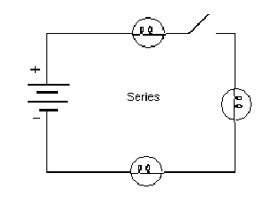
Two different types of circuits are series and parallel circuits. A series circuit is a circuit in which the components (e.g. lights) are connected in line with one another and the wire. In other words, a series circuit contains components that all “share” the same wire. A series circuit does not contain any three or more wire junctions. However, a parallel circuit is a different matter. It’s a circuit in which there are junctions of three or more wires. Components don’t “share” the same wire, instead each component has it’s own wire. When examining circuits, engineers often use pictures called circuit diagrams. Circuit diagrams are used to illustrate the pathways through which electricity can flow.
As stated earlier, electricity travels through conductors. If there is a break in the wiring, the flow of electrical current is stopped. For instance, in the series circuit shown below, the flow of current is stopped after the first light by the break in the wiring. Since there is a break in the wire, none of the lights will light up.
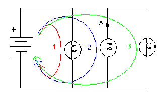
 For a parallel circuit, current has more then one path through which it can flow. As seen from the figure below, this particular parallel circuit has three different paths through which it can travel (path 1: red, path 2: blue, path 3: green). This means that if there is a break in the wire at point A in the diagram, the first and the third light bulb will still light, but the second light bulb will not. This is because current is still able to reach the other two light bulbs to light them.
Safety Issues and Troubleshooting Tips
- Make sure the holiday lights are not plugged into an outlet while the students are trying to remove the bulbs from the circuit.
- Make sure the batteries are new and that none of the lights are broken.
- Make sure all the wires are securely attached to each connection point to avoid gaps in the connections (short circuits).
ACTIVITY
Introduction/Motivation
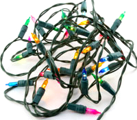
1. Plug a string of holiday lights into an outlet and explain how electrical current flows through the circuit to make the lights work (refer to the background information for reference).
2. Have students each take out a light bulb from the string of lights to see how current flows to the light bulb through the metal wires on the side of the light. Screw the light bulbs back into the light bulb holders.
Instructions to students
1. Build a simple circuit using one battery, two alligator clips, and a light bulb.
2. Attach one end of an alligator clip to the positive terminal of a battery.
3. Take the other end of the clip and attach it to one side of the light bulb holder’s conducting material (typically, another piece of metal).
4. Take another alligator clip and attach one end to the other side of the light bulb holder’s conducting material.
5. Finally, attach the free end of the second alligator clip to the negative terminal of the battery to complete the circuit.
6. Now, using the diagram below as a guide, first build a series circuit, then build a parallel circuit
Assessment
Discussion
- Ask students what would happen if the battery were turned around in the circuit. Have them explain why they think this is so.
- Ask students if they think light bulbs in series would be brighter or light bulbs in parallel. Why?
- Allow students to re-examine the string of lights and ask what happens when they remove certain light bulbs along the string of lights. Have them explain what they see in terms of circuit type.
- Have the students briefly describe the differences between a parallel and a series circuit.
- Have them draw a simple sketch of a parallel and a series circuit.
Extension
- Ask students, when buying holiday lights, what kind would be the best, in terms of circuit set up.
- Have students take a look at holiday lights they find in local stores; wired up in their neighborhood; or around town, and to see if they can tell how their circuits appear to be designed. Caution them to take care not to disturb anyone’s light display.
Activity Scaling
- For students who have a good understanding of how to build a circuit, have them build a combination series and parallel circuit.
Resources
See another eGFI electricity lesson “Electricity in a Bag“
How light bulbs work, from How Stuff Works.com
Comparing Parallel and Series Circuits, from msnucleus.org. This Web page offers a post lab in circuits.
Benjamin Franklin and Discovery of Electricity, The American Revolution, from americanrevolution.com
Electricity Tutorial, Swanson Technologies
Contributors: Wendy Lin, Creator/Editor, Pratt School of Engineering, Duke University. Copyright © 2004 by Engineering K-Ph.D. Program, Pratt School of Engineering, Duke University including copyrighted works from other educational institutions and/or U.S. government agencies; all rights reserved.
Filed under: Grades 6-8, Grades K-5, Lesson Plans
Tags: Electrical Engineering, Grades 4-9


