


Preventing Potholes
Activity courtesy of TeachEngineering, a searchable digital library of standards-based, authentic engineering curriculum developed by the Integrated Teaching and Learning Program at the University of Colorado Boulder’s College of Engineering. The activity is part of Keeping Our Roads Smooth, a 30-minute lesson that provides prerequisite knowledge of how roads are built and maintained.
Grade level: 9-12
Time: 1 hour (~30 minutes for data collection, 30-40 minutes for data analysis; plus post-activity assessment as homework)
Group size: 4
Summary
Acting as civil engineers hired by the U.S. Department of Transportation to research how to best use piezoelectric materials to detect road damage, groups of high school students are challenged to independently create their own experiment procedures, working with given materials and tools. The general approach is that they set up model roads using rubber mats to simulate asphalt and piezoelectric transducers to simulate the in-ground road sensors. They drop heavy bolts at various locations on the “road,” collecting data and then analyzing the voltage changes across the piezoelectric transducers caused by the vibrations of the bolt hitting the rubber. After making notches in the rubber “road” to simulate cracks and potholes, they collect more data to see if the piezo elements detect the damage. Students write up their research and conclusions as if presenting evidence to USDOT officials about how the voltage changes across the piezo elements can be used to indicate road damage and extrapolated to determine when roads need maintenance service.
Engineering Connection
The U.S. Department of Transportation provided Michigan State University with millions of dollars in grant money to research ways to create self-powered sensors to monitor road conditions. Current road-monitoring sensors have power limitations; batteries eventually die, and solar power won’t work for devices covered by asphalt. Researchers are currently looking at using piezoelectric materials—which convert mechanical energy to electrical energy when pressed—to harvest the energy from road vibrations to power the sensors to collect data that can be used to detect and predict damage trends.
Learning Objectives
After this activity, students should be able to:
- Evaluate changes in voltage to assess and predict road damage.
- Communicate their findings and provide evidence to support results.
- Create a list of future experiments to perform related to this research.
Learning Standards
NGSS: Next Generation Science Standards – Engineering Technology and Physical Science
- HS-ETS1-2. Design a solution to a complex real-world problem by breaking it down into smaller, more manageable problems that can be solved through engineering. (Grades 9 – 12)
- HS-ETS1-3. Evaluate a solution to a complex real-world problem based on prioritized criteria and trade-offs that account for a range of constraints, including cost, safety, reliability, and aesthetics, as well as possible social, cultural, and environmental impacts. (Grades 9 – 12)
- HS-PS3-3. Design, build, and refine a device that works within given constraints to convert one form of energy into another form of energy. (Grades 9 – 12)
Common Core State Standards – Math
- Summarize, represent, and interpret data on a single count or measurement variable (Grades 9 – 12)
- Represent data with plots on the real number line (dot plots, histograms, and box plots).
International Technology and Engineering Educators Association
- Students will develop an understanding of and be able to select and use energy and power technologies.
- Students will develop an understanding of engineering design.
Materials
Each group (four students) needs:
- 3 piezo elements, such as part # SEN-10293 ROHS for $1.50 each from SparkFun
- Vernier LabQuest handheld device, such as Vernier’s LabQuest Mini that attaches to a computer with the Logger Pro 3 software installed, for $169 each
- Differential voltage probe, such as Vernier’s DVP-BTA differential voltage probe for $39 each
- Piece of rubber matting, ~50 x 25 cm, to represent an asphalt road; such as cut from 8 mm-thick 4 x 10 ft roll of plyometric black gym rubber floor material for $130-200 at Greatmats; this roll of solid black rubber is enough to make ~30 model “roads.”
- Heavy, large bolt and nut, such as from Home Depot’s 25-pack of 3/8-inch x 1.5-inch zinc hex bolts for $5.22 and corresponding 100-pack of 3/8-inch 16 tpi zinc-plated hex nuts for $9.57
- 1 pair of scissors
- Temporary adhesive, such as tape or glue stick, to adhere the piezo elements to the rubber mat
- (optional) Plastic bin or cardboard box to contain the above materials, for easy distribution
- (optional) Digital camera or phone, to document the experiment and results for the final letter
- Computer with Logger Pro 3 interface software from Vernier; a $249 school-wide license enables installation on an infinite number of computers, including student devices
- Microsoft® Excel® loaded on the computer, for data recording and graphing
- Microsoft® Word® loaded on the computer, for final letter preparation
- Paper and pencil
Prerequisite Knowledge
Familiarity with designing experimental procedures and data tables, including how to test for changes in one variable at a time with given controls. Students must know how to work the Vernier LabQuest, differential voltage probe and Logger Pro 3.
Introduction/Motivation
(Begin this after the close of the discussion from the associated lesson, Keeping Our Roads Smooth.)
The U.S. Department of Transportation (USDOT) has hired your engineering firm to determine how the use of piezoelectric transducers can provide a way to self-power road sensors and generate ongoing useable data for the tracking and prediction of damage on roadways. You and your group must conduct research to determine how these piezoelectric transducers can help show road damage. The agency is spending hundreds of millions of dollars on this project and reliable data must be shown so that the engineers can proceed with the next aspect of highway planning.
Your engineering challenge is to figure out how the piezoelectric transducers inform us of impending damage. You also need to inform USDOT on whether the piezoelectric transducers predict local or global damage. Your team will receive three piezoelectric transducers, a voltmeter, a piece of rubber matting to simulate the asphalt, and a heavy bolt. Within your group, discuss the best way to conduct tests in order to answer these questions. That means you need to determine what needs to be tested, create a procedure and design graphs to show the data. (Proceed to organize the class into groups, distribute the materials, and let students begin.)
Procedure
Background
In this activity, students drop heavy bolts onto rubber mats onto which three piezo elements have been adhered. This setup models an asphalt roadway with embedded piezoelectric sensors. After recording the voltage reached by each element, they analyze how damage can be detected and located on a road.
Before the Activity
- Purchase enough piezoelectric elements so that each group has three.
- Purchase enough rubber matting so that each group has a piece with dimensions of 50 x 25 cm; the thickness does not matter as long as it is less than 1 cm thick—for vibrational purposes. Cut the rubber roll into individual pieces, one per team.
- (optional) Collect in a plastic bin or cardboard box for each team, the piezo elements, rubber piece, Vernier LabQuest, differential voltage probe, and bolt and nut. Doing this makes it easier to distribute each team’s materials.
- Make sure Logger Pro 3 is installed on all computers being used for this activity.
With the Students
- Present to the class the Introduction/Motivation content. Then divide the class into groups of four students each.
- Circulate as groups each work on coming up with an experimental procedure and data table. An example procedure is provided below. Let students drive the procedure, giving only limited teacher input. The teacher serves as a guide to help students when needed. Tip: It may be helpful to provide a list of materials before they begin creating their procedures so as to limit what they can use and help ensure that they are designing procedures that are repeatable in the classroom.
- Based on what students already know about piezoelectricity and piezoelectric transducers, have them hypothesize how each of three transducers will behave as the “road” becomes damaged.
- Students temporarily attach the piezo elements to the piece of rubber at three locations (see Figure 1). To provide accurate results, ideal placement of the piezo element is at least 3 cm from the end of the rubber “road” and 20 cm from each other. Label the piezo elements, such as A, B and C.
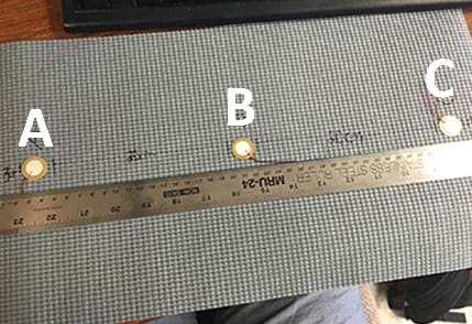
Figure 1. An example activity experimental model “road” setup. All photos © Adam Alster, RET Program, College of Engineering, Michigan State University
5. Connect the differential voltage probe to the LabQuest.
6. Use the provided USB cable to attach the LabQuest to the computer.
7. Open Logger Pro 3 on the computer. If the setup is correct, expect the computer to read 0 volts. If it is not reading 0 volts, zero it by right-clicking on the lower left-hand corner where the voltage is displayed. Click “zero” to zero the probes.
8. With the nut on the bolt (to make it heavier), hold it 25-30 centimeters above the rubber (see Figure 2). This procedure depends on the nut/bolt weight and the rubber thickness, so adjust accordingly; students’ procedures may vary, of course.
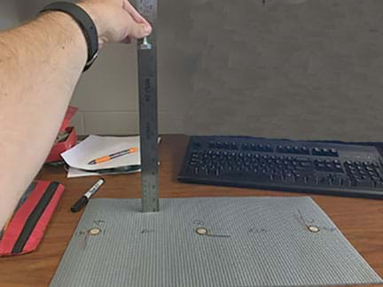
Figure 2. Dropping a nut/bolt. © Adam Alster, RET Program, College of Engineering, Michigan State University
9. As one student drops the nut/bolt, another team member hits the green play button to start data collection. The differential voltage probe collects data and displays a voltage vs. time graph (see an example in Figure 3). Students record the largest voltage measured on the graph.
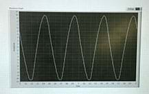
Figure 3. An example voltage vs. time graph. © Adam Alster, RET Program, College of Engineering, Michigan State University
10. Repeat steps 8 and 9, moving the bolt near each of the three piezo elements.
11. Using a pair of scissors, simulate a roadway pavement crack by making a notch near one of the piezo elements—only one. This enables testing for local vs. global damage. Local damage refers to damage that is near the piezoelectric element; this tests for damage at a specific location. Global damage refers to damage anywhere on the mat, not just near a transducer. Make the notch large enough to show “damage,” but not too large. See Figure 4 for examples of “good” notches and Figure 5 for examples of “bad” notches.
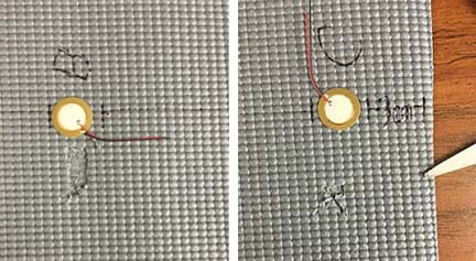
Figure 4. Example “good” notches that represent pavement damage.
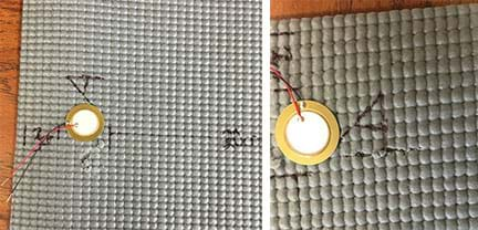
Figure 5. Example “bad” introductory notches.
12. Repeat steps 8-10 to collect data now that notches (damage) have been added.
13. Students make the initial notches deeper so that they resemble/represent larger potholes (see Figure 6).
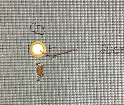
Figure 6. Example of a second-round, deeper/bigger notch.
14. Repeat steps 8-10 to collect data with the deeper/bigger notches (road damage).
15. Once data collection is completed, have students create line graphs using Excel®, then analyze their data and come up with conclusions.
16. As described in the Assessment section, lead a concluding class discussion and then assign students homework to individually write letters to the U.S. Department of Transportation explaining their findings and describing why the USDOT should fund this ongoing research, with supporting data.
Vocabulary/Definitions
- damage: Changes to a material and/or the geometric properties of a structural system that adversely affect its performance.
- energy harvesting : Obtaining energy from external sources (solar, wind, thermal, kinetic, etc.) to create, store and use electrical energy.
- global damage: Damage located somewhere on the road with the precise location unknown.
- local damage: Damage in a specific location.
- piezoelectric effect: A process by which a material converts a mechanical force into an electrical response. In other words, deforming a material to generate an electrical potential (or voltage).
- piezoelectric transducer: A piezo element that generates a voltage change when pressure is applied.
- road design: Analysis of the land, traffic volume, ratio of cars to trucks, future development to the design of a road or bridge. Also called highway engineering.
- road earthwork: The establishment of a stable foundation for road creation by moving and shaping the soil and rock to build embankments, compacting the soil to maximum density, installing sewers, drains and curbs, etc.
- road paving : The placement of asphalt or concrete on top of the preparatory earthwork.
Assessment
Post-Introduction Assessment
Hypothesis and Procedure: To begin the experimental work, have students first individually record their hypotheses on paper, drawing on what they learned in the associated lesson. Then they work in groups to create workable procedures and data tables in which to collect and record data as they perform experiments that meet the challenge presented in the Introduction/Motivation. Important: The experiments are to be designed by the groups, not the teacher. The teacher circulates the working groups, not to provide a procedure, but to guide students to a workable procedure only if needed, and only by asking probing questions. Remember—this is student-created experiment!
Activity Embedded Assessment
Probing Questions: As students work, circulate the classroom asking the following questions to guide their thinking and assist as needed. As you circulate the room, ask the groups these questions and record their answers. All the questions need not be asked simultaneously of each group, but rather, throughout the activity as makes sense. Gathering student responses guides the teacher during the post-activity assessment when the answers are discussed.
- How far can the sensor (piezo element) be from the damage to detect it? (Example answer: The piezo element can be placed ~1.5 cm from the damage to effectively detect the damage.)
- How reliable are these elements at detecting and locating damage? (Example answer: The elements are very reliable when detecting and locating damage when the element is within 1 cm of the damage. Other than that, they are not reliable in detecting or locating the damage.)
- If USDOT were to strictly use piezo elements to detect damage, what are the limitations? How can we use the piezo elements to make a more global detection system? What needs to be further researched? Why? (Example answer: If the USDOT only used piezo elements to detect damage, the limitations would be that they would only know the location of damage that occurred near sensors. If the collected data was from sensors that were far from some damage, then no indication of damage would be found and engineers would be unaware of that road damage. That suggests that the piezo elements need to be placed every few inches along the road, but that would be expensive. Therefore, it becomes important to research the development of elements that are capable of detecting global damage.)
- How do these sensors tell us if damage exists on a road? What changes, and how? (Example answer: As a road’s damage progresses, the vibrations on the road increase. This increases the generated voltage, and is reflected in the collected data. An increase in voltage signifies increasing road damage.)
Expected Results: In this activity, there are expected results that students should see. Below are examples of these results from examining the setup shown in Figure 1, as damage is introduced at position B.
- Expect the voltage readings for all positions, A, B and C, to initially vary, depending on the nut/bolt weight and the initial drop height.
- As damage is introduced near position B, students see that both piezo elements, A and C, produce similar voltages to the initial ones they recorded. However, at position B, the voltage increases because more strain exists on the rubber at this location and more strain produces a larger voltage output.
- As more damage is introduced, the piezo element at location B has an even greater increase in output voltage; more damage implies more strain. However, the piezo elements at locations A and C still do not register a change in output voltage.
- Note that a piezo element that is located near damage produces a greater voltage as the damage increases, while piezo elements farther from the damage do not register a significant change in output voltage. This is because the element closest to the damage receives more strain as the damage increases. As for the other elements, the strain level is consistent.
- The next step for students to investigate is: how can we detect damage on a larger scale vs. the exact damage location. For instance, if damage occurs between two piezo elements, how can that damage be assessed? Encourage students to try this if they wish.
Post-Activity Assessment
Concluding Discussion: After groups have created Excel® graphs with their collected data, but before they begin the letter homework assignment, go over the probing questions/answers (see the Embedded-Activity Assessment, above) in a class discussion format. Make sure that students understand their research results and what the data implies, which will help them write their letters.
Homework
Letter to USDOT: As homework, assign students to individually write (hypothetical) letters to the U.S. Department of Transportation on the use of piezoelectric elements to predict, detect and locate road damage, explaining their research findings and describing why USDOT should fund this ongoing research, with supporting data and ideas for future research to advance the technology. Remind students that this is a letter, not a lab report, and to structure it as a professional business letter (even though it might be a long letter). Require each letter to include the following components:
- An introduction explaining the problem to be investigated.
- A hypothesis explaining what was anticipated to be discovered and the scientific reasons why.
- The experimental procedure; experiment photographs and/or diagrams are helpful.
- Collected data in the form of computer-generated tables and graphs.
- A discussion of the results and analysis, such as what it means in terms of using the piezo elements to predict, detect and locate road damage.
- A conclusion that includes a summary of the experiment, results with their implications and limitations, and suggestions for future research that is needed to improve the idea.
Safety Issues
- Be aware of your surroundings as bolts are dropped.
- Keep laptop cords tucked away to prevent tripping.
Troubleshooting Tips
As a help resource for the Vernier equipment, visit Vernier’s product support page, which provides “troubleshooting and FAQs” for its interfaces, software, sensors and lab equipment.
Activity Extensions
Have students look at scholarly articles about piezoelectric transducers and analyze their significance in civil engineering. This research might be used to further support their USDOT letters. In addition, it helps students see how their experimental research mimics current research on this topic.
Challenge students to examine how piezoelectric accelerometers can detect damage. The transducers detect only local damage while accelerometers detect global damage. For example, a transducer can pinpoint exactly where damage is located while an accelerometer detects damage on the road, but not at a precise location. Students could use the same piezo elements used in the activity and elevate them on the “road” to create accelerometers.
Activity Scaling
- For lower grades, provide more guidance by holding a class-wide discussion about developing the procedure.
- For younger grades, have student groups record their data on the classroom board and the teacher graph the data in Excel® for review as a class.
- For students who are not familiar with Vernier technology, guide them through the program and interfaces before beginning the activity.
References
Chatti, Karim. “An Intelligent Structural Damage Detection Approach Using Self-Powered Wireless Sensor Data.” March 2014. Presentation, Research Experience for Teachers, Michigan State University, East Lansing, MI.
Lajnef, Nizar, Karim Chatti, Shantanu Chakrabartty, Mohamed Rhimi, and Pikul Sarkar. “Smart Pavement Monitoring System.” May 2013. Technical report from the Research, Development and Technology Turner-Fairbank Highway Research Center, McLean, VA; Federal Highway Administration, U.S. Department of Transportation. Publication number FHWA-HRT-12-072.
Lynch, Jerome P. and Kenneth J. Loh. “A Summary Review of Wireless Sensors and Sensor Networks for Structural Health Monitoring.” March 2006. The Shock and Vibration Digest, Vol. 38, No. 2, pp. 91-128.
Park, G., Farrar, C.R., Todd, M.D., Hodgkiss, W., Rosing, T. 2007. “Energy Harvesting for Structural Health Monitoring Sensor Networks,” Los Alamos National Laboratory Report, NM; LA-14314-MS.
Sohn, Hoon, Charles R. Farrar, Francois M. Hemez and Brett R. Nadler. “A Review of Structural Health Monitoring Literature: 1996 – 2001.” January 2004. Los Alamos National Laboratories, NM; LA-13976-MS.
Structural Health Monitoring. Last updated June 24, 2016. Wikipedia, the free encyclopedia. Accessed June 25, 2016.
Copyright
© 2016 by Regents of the University of Colorado; original © 2016 Michigan State University
Contributors
Adam Alster; Victoria Davis-King; Amir Alvai; Nizar Lajnef; Drew Kim; Andrea Varricchione
Supporting Program
Smart Sensors and Sensing Systems RET, College of Engineering, Michigan State University
Acknowledgements
This curriculum was developed through the Smart Sensors and Sensing Systems research experience for teachers under National Science Foundation RET grant no. CNS 1609339. However, these contents do not necessarily represent the policies of the NSF, and you should not assume endorsement by the federal government.
Filed under: Class Activities, Grades 9-12, Lesson Plans
Tags: asphalt, highway construction, NGSS aligned activity, pavement, piezoelectric materials, pothole repair, road repair, Sparkfun, TeachEngineering activity, transportation engineering, Vernier