Paper Circuits Greeting Cards
 Time: 1 hour
Summary
Create a sure-to-impress light-up paper card—no soldering required! In this activity, students create simple paper circuitry using only copper tape, a coin cell battery, a light-emitting diode (LED), and small electronic components such as a LilyPad Button Board. A great way to teach the basics of how circuits function while giving students an outlet to express their artistic creativity.
Engineering Connection
Electronic circuits are at the core of nearly every new technology. Circuits power cell phones, computers and televisions, and are essential in cars, houses and kitchens. Circuits are everywhere and modern innovations would not be possible without them. Circuits enable electricity to flow between speakers, bulbs, buzzers, sensors, buttons and batteries. When engineers design new technologies, they often design and build companion electronic circuits so the technology functions as intended. In this activity, students are reminded about how electronic circuits work and then build their own circuits using simple, easy-to-use materials and provided templates (three designs). A PowerPoint® presentation is provided.
Pre-Req Knowledge
Some familiarity with electronic circuits and a working knowledge of the function of LEDs, batteries and wires. If new to working with electronics, see the Additional Multimedia Support Section for suggested online resources.
Learning Objectives
After this activity, students should be able to:
- Design a product (a light-up pop-up greeting card) from a template, utilizing symbols and a model.
- Troubleshoot and iterate through different designs.
- Explain how a paper circuit works, including which electrical components accomplish which task.
Learning Standards
Next Generation Science Standards
- Make observations to provide evidence that energy can be transferred from place to place by sound, heat, light, and electric currents (Grades PS-3)
- Forces at a distance are explained by fields (gravitational, electric, and magnetic) permeating space that can transfer energy through space. Magnets or electric currents cause magnetic fields; electric charges or changing magnetic fields cause electric fields. (Grades 9 – 12)
- …and “electrical energy” may mean energy stored in a battery or energy transmitted by electric currents. (Grades 9 – 12)
Common Core Literacy Standards
- Follow precisely a complex multistep procedure when carrying out experiments, taking measurements, or performing technical tasks, attending to special cases or exceptions defined in the text. (Grades 9 – 10)
- Determine the meaning of symbols, key terms, and other domain-specific words and phrases as they are used in a specific scientific or technical context relevant to grades 9—10 texts and topics.
International Technology and Engineering Educators Association
- Systems, which are the building blocks of technology, are embedded within larger technological, social, and environmental systems. (Grades 9 – 12)
- Engineering design is influenced by personal characteristics, such as creativity, resourcefulness, and the ability to visualize and think abstractly. (Grades 9 – 12)
Materials List
Each student/card needs:
- adhesive-backed copper tape, 5-mm width, ~18-inches per card; such as from a spool of 50 feet for $3 from SparkFun – available HERE.
- 1 (or more) LED; use the smallest size you can find so it does not add much bulk to the folded greeting card, such as 3-mm size for 35¢ each; for extra flair, consider using 3-mm, color-changing cycling RGB LEDs for 50¢ each; alternatively, cut apart individual LEDs from a set of LET string lights and then use a hobby knife to scrape the coating off the wires before using OR experiment with different LEDs to find what works best for the project objectives
- coin cell battery, 12-mm size, such as SparkFun’s CR1225 for $1.95
- LilyPad Button Board for $1.95 OR LilyPad Slide Switch for $1.75
- 2 sheets of cardstock, 8.5 x 11-inch, may be different colors, on which the teacher prints a template
- I <3 U Template, Pixel Heart Template or Frame Template, one template per student/card; printed out on cardstock (2 pages per template)
- (optional) vellum or parchment paper, to create a diffused effect for LEDs, such as in the center of the heart in the I <3 U design
- scissors or hobby knife (can share among a few students)
- needle nose pliers, to bend wire (can share among a few students)
To share with the entire class:
- clear tape
- glue stick or glue
- decorating supplies such as stickers, markers, paper and paints, to embellish card designs
- Making Light-Up Pop-Up Greeting Cards Presentation, a PowerPoint® file, to project to the class, make selected handouts or use as a teacher preparation resource. Click HERE for PDF.
Introduction/Motivation
Have you ever wanted to give someone a Valentine’s card or a greeting card of some kind, and wanted to really impress them? Are you feel limited or bored with making the same old drawings with pencil, pen or marker? Did you know it is possible to create greeting cards that light up? Well today is your chance to make the best Valentine’s Day (or birthday, Arbor Day, holiday, etc.) card ever!
In this activity, you will get to design, customize and create your own light-up card that is powered with a mini battery, an LED (or multiple LEDs), and a circuit made of copper tape. Your design is totally up to you, but templates are available if you want some ideas. (Adjust the previous sentence depending on the teacher’s planned use of the provided three templates.)
A very important aspect of engineering is creativity. Engineers often need to think creatively in order to dream up the amazing new technologies that have never existed before. It is not possible until you dream it, so today is your chance to think like an engineer and create something special and all your own!
Vocabulary/Definitions
- circuit: A roughly circular line, route or movement that starts and finishes at the same place.
- electricity: The transfer of energy resulting from the flow of charged particles (such as electrons).
- electron: A subatomic particle found in all atoms and acting as the primary carrier of electricity in solids.
- paper circuit: A low-voltage electronic circuit created on paper using conductive copper tape, LEDs and a power source such as a small battery.
Procedure
Before the Activity
- Gather materials.
- Print the greeting card templates on cardstock: I <3 U Template, Pixel Heart Template and Frame Template, one template per student/card. You may want to pick just one template that every student makes, or print an assortment of the provided three templates, or make the activity more free-form and not use the provided templates. Tips: Printing the templates might require that you adjust your printer’s margins or choose the “Fit to Page” print setting. The card template is slightly smaller than standard 8.5 x 11-inch paper, so make sure to cut along the outer black border (or have students do this) for the final cards.
- Set up a computer and projector to show the class the 13-slide Making Light-Up Pop-Up Greeting Cards Presentation, a PowerPoint® file. Click HERE for PDF version. Alternatively, as makes sense for your class, just show/make handouts of certain slides for students or use the slides as a teacher preparation resource.
With the Students
- Begin with the pre-activity assessment about basic circuitry. Present the Introduction/Motivation content to the class. Then hand out the supplies and begin the presentation.
- Create copper traces: Begin the project by using copper tape to create a path for electricity. Notice that the card templates have icons to help in constructing the circuit; notice the symbols for cut, fold, copper tape, cut tape, LED, button and battery (see slide 5).
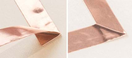
- Line B: Place copper tape along Line B, which includes a corner. To keep a solid connection of copper around corners, use a folding technique to press the tape into the shape (see Figure 1 and slide 6).
- Line A: Look at the template and find a circle marked A. Peel away a few inches of the paper backing from the copper tape and stick it down along the gray line. Cut the tape when you reach the scissors icon.
- Start by sticking the copper tape down along Line B until you reach the corner.After the copper tape reaches the corner, start to fold the tape backward on itself. Use a fingernail or pen to give it a good crease along the fold.
- Fold the tape back to approximately the width of the gray line and then carefully move the tape at a right angle from the copper tape already taped down. Notice that a second fold forms out of the corner point. Press the second fold down and then tape it flat against the paper. Note that the neatness of the fold does not matter too much since it will be covered by the pop-up in the end.
- When you reach the scissors icon, cut the tape.
Figure 1. How to turn a corner with copper tape
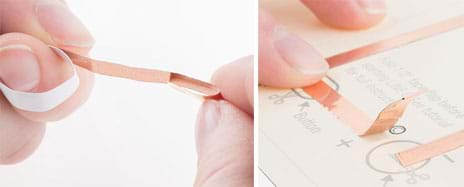
5. Line C: This stretch of copper tape also forms a battery holder (see Figure 2 and slide 8).
- Start by folding one-half inch of copper tape onto itself, sticking the adhesive sides together to form a flap. Doing this enables the top of the copper to fold down over the coin cell battery. Since the battery’s positive side is the top and its negative side is the bottom, doing this creates a “battery sandwich” with copper tape touching each side.
- We will not install the battery until the end of the project, so leave the flap be and lay the copper tape down along Line C, making a similar fold at the corner as previously done for Line B.
- When you reach the scissors icon, cut the tape.
Figure 2. How to make a battery holder with a flap of tape.
6. Fold the card in half along the dotted center line before moving onto the next step. Tip: It is easier to make a crisp and neat fold now, before the circuit components are added to the paper.
7. Prepare and place the LED(s): Now that the copper is in place, it is time to add the light. Each template has an LED symbol that shows a shaped wire. Using this method helps us remember which LED side is positive or negative. Share with the class the following excerpt from the light-emitting diodes tutorial about LED polarity:
- In electronics, polarity indicates whether a circuit component is symmetrical or not. LEDs, being diodes, only permit current to flow in one direction. And no current flow means no light. Luckily, this also means that you cannot break an LED by plugging it in backwards. Rather, it just won’t work. The positive side of an LED is called the “anode” and is marked by having a longer “lead,” or leg. The other, negative side of the LED is called the “cathode.” Current flows from the anode to the cathode and never in the opposite direction. A reversed LED can keep an entire circuit from operating correctly by blocking current flow. So if adding an LED seems to break your circuit, try flipping it around.
8. Bend a standard LED to prepare it for the circuit (see Figure 3 and slide 9):
- Using pliers (or your finger), bend flat the longer leg of the LED. Then shape the wire into a zigzag shape. Be careful not to break the wire by bending back and forth over the same bend too many times.
- Next, bend the other leg flat and curl it into a spiral by using the tip of a pliers to lightly grab the end of the wire and curl it around the tool.
- Once all wire shaping is complete, place the LED on a table or flat surface to make sure it lays flat and with the bulb upright. If not, make any adjustments now.
- Line up the positive (longer) LED lead with the copper tape marked + (plus) and the negative with – (minus). Use clear tape over the wire to hold it down to the copper.
Fig. 3: How to bend and position LED wires
9. Attach a button/switch: Next, place the LilyPad button on the oval icon on the template, facing up (see slide 10). It does not matter which side touches positive and negative. Make sure the conductive pads on the bottom of the button touch the copper tape, then tape down the ends with clear tape. Be careful not to tape directly over the push part of the button or it may interfere with the ability to press it. As an alternative, use a LilyPad switch instead of a button; the installation is the same.
10. Insert a battery: Once all the components are installed, test the circuit by adding a battery (see Figure 4 and slide 8). Carefully slip the battery underneath the copper tape flap made earlier and center it inside the circle icon. Make sure the positive side of the battery (top, marked with the battery model and +) is facing up. Press the copper flap over the battery, and tape it down with clear tape.
11. Now, press the button, and the LED should light up! See the Troubleshooting Tips if it does not.
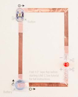
Fig. 4. The finished i<3 U circuit.
12. Prepare the pop-up: Now cut out the pop-up pieces and do some careful folding (see slides 11-12). As needed, click the links below for detailed guidance on assembling the pop-up cards.
-
- I <3 U instructions: It is easiest to glue a piece of vellum or parchment paper to the back of the heart outline before folding this pop-up. Since the original project is in Korean, you may want to watch this (4:27-minute) YouTube video tutorial that shows the process.
- Pixel heart instructions: This card can be tricky to pop up since it has so many small cuts. It helps to use a pencil or thin marker to pull up the folds one at a time from the bottom of the heart up to the top.
- Frame instructions: The folding instructions for the window card at this Christmas Pop-Up Card tutorial are helpful. Place a piece of parchment paper or vellum behind the frame to create a base on which to attach stickers or cut outs, or to draw on with markers. This template is a blank canvas awaiting students’ unique messages and scenes.
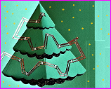
Fig. 5 Finished pixel-heart card.
13. Assemble and finish:
-
- When the pop-ups are constructed and ready to light up, carefully place them over the copper tape circuit. Glue or tape the corners down to adhere to the backing (see Figure 5 as an example). Gently fold down the pop-up to close the card.
- Finally, use a marker or stickers to indicate where to push the button.
- Add additional decorations to make the card extra special.
14. Conclude by asking the post-activity reflection questions as described in the Assessment section.
Attachments
Safety Issues
- Never connect the positive and negative terminals of a battery directly together as this causes a short circuit and the connecting material may become very hot.
- Depending on the age of the students, have them especially use care with the hobby knives, which are very sharp.
Troubleshooting Tips
Most activity snags are solved by emphasizing the importance of a “continuous circuit.” Doing this encourages students to check for loose and broken interconnections, or torn circuit elements. When in doubt, substitute a new circuit element (that is, an LED, battery, button, wire, etc.). Other tips:
- Check the tape connections: Use a fingernail or pencil to make sure the tape is firmly adhering the components to the copper tape.
- Check the battery: Make sure the battery is sandwiched firmly between the top and bottom copper tape lines and that the top copper does not accidentally touching the bottom of the battery.
- Check the LED wires: Double check that the wires did not accidently break while bending them into shapes with the pliers.
Assessment
Pre-Activity Assessment
Prior Knowledge: In an informal discussion, quiz students about the key elements of basic circuity to see what they know about the essential circuit components and the importance of creating a continuous circuit. As necessary, refer to the diagram on slide 2 in the Making Light-Up Pop-Up Greeting Cards Presentation.
Activity Embedded Assessment
Engagement: Observe students during the activity to make sure each makes forward progress and does not get stuck at any step of the process.
Post-Activity Assessment
Reflection Questions: As a class discussion or a journal writing assignment, ask students the following questions:
- What is the minimum number of parts you needed to make your finished product? Name them.
- What was one problem you encountered and how did you overcome it?
- What is your most favorite aspect of your design?
- What makes your design unique?
- What improvements or new ideas would you implement in designing another light-up greeting card?
Activity Extensions
Try these techniques with other pop-up designs or have students create their own. Ask students: Can you figure out how to adapt the copper tape path to fit your card choice? Further ideas and card variations:
- E-Craft Resources: Downloadable templates and activities about e-crafting.
- Let It Glow Holiday Cards: Paper circuit templates for the holidays.
- Light-Up Father’s Day Card: A glowing card using copper tape and soldering skills.
Activity Scaling
For more advanced students, challenge them to add more LEDs and/or sensors and buzzers to their greeting card paper circuits.
Additional Resources
SparkFun’s helpful diagram for making paper circuits: https://learn.sparkfun.com/resources/65
If new to working with electronics, check out these helpful readings: 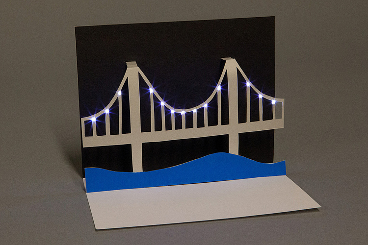
References
Activity adapted from SparkFun and Angela Sheehan’s Light-Up Valentine Cards activity.
Contributors
Angela Sheehan; Devin Rourke
Copyright
© 2017 by Regents of the University of Colorado; original © 2014 SparkFun Education
Filed under: Class Activities, Grades 6-8, Grades 9-12, Lesson Plans
Tags: Class Activities, electricity, Grades 6-8, Grades 9-12, LEDs, Lesson Plan, NGSS, paper circuits greeting cards, Physics, STEAM, Technology


