Hydraulic Arm Challenge
[youtube]http://www.youtube.com/watch?v=sicZuYnMMuA[/youtube]
TeachEngineering activity contributed by the Center for Engineering Educational Outreach, Tufts University.
Summary
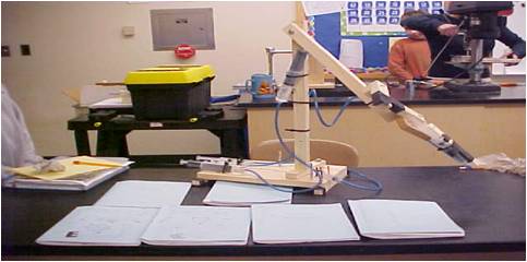
Teams of students in grades 6 to 8 follow the engineering design process to develop and build a mechanical arm that can lift and move an empty 12-ounce soda can using hydraulics for power. One group designs and builds the grasping hand, another team the lifting arm, and a third team the rotation base. The three groups must work to communicate effectively through written and verbal communication and sketches.
Grade Level: 6 to 8
Time: 180 minutes (4 to 5 class periods)
Engineering Connection
Learning Objectives
- Identify the steps of the engineering design process.
- Recognize the steps of the engineering design process as they design and build.
- Represent solutions to a design process in multiple ways.
- Describe and explain features and purpose of a design.
- Explain the basic concepts of hydraulic and pneumatics.
Standards
Next Generation Science Standards
- Evaluate competing design solutions using a systematic process to determine how well they meet the criteria and constraints of the problem.
- Develop a model to generate data for iterative testing and modification of a proposed object, tool, or process such that an optimal design can be achieved.
Common Core State Mathematics Standards
- Construct and interpret scatter plots for bivariate measurement data to investigate patterns of association between two quantities. Describe patterns such as clustering, outliers, positive or negative association, linear association, and nonlinear association.
International Technology and Engineering Educators Association
- K. Test and evaluate the design in relation to pre-established requirements, such as criteria and constraints, and refine as needed.
Materials
- plastic syringes (source: online McMaster-Carr, $1 per syringe)
- plastic tubing (source: pet supply store, $20)
- various wood scraps
- bolts, screws, nuts, washers
- other APPROVED materials
- 1 empty soda can
- tape
- 20 x 20 piece of wood or cardboard to serve as a wall
- drill (for teacher use or with appropriate supervision)
- saw (for teacher use)
- empty soda can
Introduction/Motivation
Vocabulary/Definitions
- hydraulics: Involving or moved by fluid under pressure.
- prototype: A working model of a new product or new version of a product.
- pneumatics: Involving the mechanical properties of air and other gases.
Safety Factor(N): A number used to describe how much more force your device should withstand past the max expected force based on a number of parameters such as material and dimensions (N=1 means only can withstand 100% of expected force, so it will fail at 101% of expected load).
Procedure
Suggested Timing
- Part 1 – Investigating Pneumatics and Hydraulic Systems Handout: 1 ½ – 2 class periods at 40 minutes each.
- Part 2 – Creating the hydraulic arm: three 40-minute classes (This activity can be done in fewer class periods, but giving students this amount of time enables them to test numerous design ideas and further understand the engineering design process and the underlying concepts.)
Background
Before the Activity
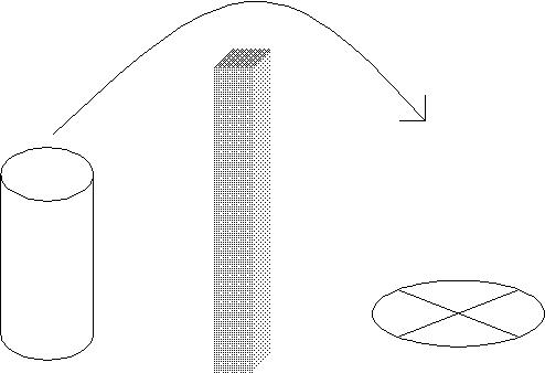
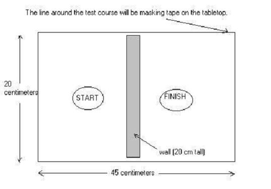
Build a soda can test area that is 20 x 45 centimeters. Use tape to mark the perimeter of the test area. Place a 20 x 20 cm tall wall in the middle of the test area so the area is divided into two equal areas, each measuring 20 x 22 cm. Draw a circle on each side of the wall. Write “Start” in one and “Finish” in the other. The circles should be ~4 centimeters from the wall and 6 centimeters from the sides. These dimensions are flexible. Smaller would be easier and larger dimensions are harder.
Images copyright © 2006 Center for Engineering Educational Outreach, Tufts University
- Make copies of the journals and handouts.
- Gather materials.
With the Students
- Research the engineering design process and answer the questions on the Investigating Pneumatics and Hydraulics Systems Student Handout.
- Research possible solutions to the challenge. Tips: Look for pictures of other mechanical arms (or parts of arms) that perform functions similar to the ones that they must perform. Think about the connection between their team’s component and the components it is connect to. The connections are the most challenging part!
- Develop a portfolio (a bunch) of sketches that attempt to solve the problem. Share with the entire design team. Upon identifying a promising design, brainstorm with the next design team regarding attaching them together. Critique (be nice, constructive) the designs and make a short list of pros (+) and cons (-) for each idea. Identify the best ideas and vote to decide upon them.
- Make final engineering sketches of the parts that are needed.
- Construct the prototypes, noting changes, modifications, failures and successes. It is perfectly fine to mark up your engineering sketches. Show your work!
- Test the prototype. TRY TO MAKE IT FAIL. What do you have to do to get it to fail? Can you redesign it to prevent that from happening? Make your design the best it can be. (Students like to make their designs fail. They understand that as an instruction and see it as a good mindset for testing prototypes.)
- Write down information on how long it took for your device to fail.
- Redesign and reconstruct.
- Retest.
- Once satisfied, plot your found data to see how your device improved as you modified it.
- Present the portfolio of marked-up drawings, the finished arm, and demonstrate the arm to the class.
Attachments
Safety Issues
References and Additional Resources
Hydraulic Arms Challenge. Carpenito, K. and E. Chilton. Posted January 2006; accessed November 7, 2011. (activity inspiration)
Hydraulic Arm Research. Posted January 27, 2006. Beebe School of Engineering. Accessed November 7, 2011. (a list of references to support this activity, including info on the arm joint and the engineering design process)
How Hydraulic Machines Work. Brain, Marshall. How Stuff Works. Accessed November 7, 2011.
Hydraulic Hand, Mano Hidráulica YouTube video of a homemade hydraulic robotic hand (right). 
Syringe-activated Mechanical Arm An 8th grader’s hydraulic arm in action. [YouTube 1.30]
Robotic Hands and Arms. A 2008 Raytheon presentation to NASA.
Introduction to Robotics. A series of hands-on aerospace engineering activities, including designing robotic arms, with real-life examples from space exploration developed by the Civil Air Patrol’s Aerospace Education division.
Build a Robotic Arm. PBS Design Squad activity that uses the engineering design process to create an arm that cam pick up an empty cup.
Contributors
Eric Chilton, Karen Carpenito, Elissa Milto
© 2013 by Regents of the University of Colorado; original © 2006 Worcester Polytechnic Institute
Filed under: Class Activities, Grades 6-8, Grades 6-8, Lesson Plans


